
Modern Camera Lens Repair: A Deep Dive into Circuitry Diagnostics
For many of us in the development world, our passion for technology often extends beyond code into the realm of hardware. One fascinating intersection is the intricate mechanics and sophisticated electronics found in
For many of us in the development world, our passion for technology often extends beyond code into the realm of hardware. One fascinating intersection is the intricate mechanics and sophisticated electronics found in modern camera lenses. As a personal endeavor, I've taken to salvaging and repairing broken lenses, a unique challenge that combines precision mechanical work with meticulous circuit analysis. This pursuit not only scratches an intellectual itch but also provides an affordable way to expand a gear collection.
Our subject for today is a Sigma 45mm f/2.8 lens, acquired at a significant discount due to a reported malfunction. Upon arrival, the lens appeared pristine – no cosmetic damage, no scratches on the elements. However, mounting it to a Lumix S5 camera revealed its electronic woes: the camera recognized the lens, displayed a live image, but all electronic controls, including aperture, focus dials, and camera-body interactions, were completely unresponsive. This pointed squarely to an electrical fault within the lens's control system, typically located on the rear PCB near the contact block.
Essential Toolkit for Lens Surgery
Before delving into the delicate internal components, having the right tools is paramount. The barrier to entry isn't excessively high, but precision is key. Beyond standard lint-free wipes, isopropyl alcohol, and filtered air, a few specialized items are crucial:
- JIS Screwdrivers: Given that much of the camera industry is based in Japan, JIS (Japanese Industrial Standard) screws are prevalent. While a Phillips head might work, using the correct JIS driver prevents cam-out and preserves screw heads. I recommend both JIS x 2.5mm and JIS x 3.0mm.
- Scalpel & Plastic Spudger: For delicate prying and separating components without causing damage.
- Magnifier/Optic: Essential for inspecting tiny components and solder joints.
- Multimeter: Indispensable for checking continuity, voltage, and resistance.
Systematic Disassembly: A Developer's Approach
Approaching lens disassembly requires a methodical, almost algorithmic process. I start by orienting the lens consistently to aid reassembly. The first steps involve removing the rear plastic beauty spacer and its three black machine screws, followed by two nickel-plated screws securing the plastic lens block terminal interface to the metal mount. I use double-sided tape to organize screws in their exact removal order and orientation, a simple trick that significantly streamlines reassembly.
Next, the lens mount bayonet and its accompanying shims are carefully removed. Maintaining their order and orientation is critical for preserving the lens's optical calibration. Any imperfections or contamination on these surfaces should be cleaned with isopropyl alcohol. With the mount off, the flexible polyimide cable connecting the contact block to the control PCB becomes accessible. These flex cables are notoriously fragile, so careful handling is a must. Before proceeding, a continuity check of each trace on the flex cable with a multimeter is a vital diagnostic step; visible tears should be repaired first.
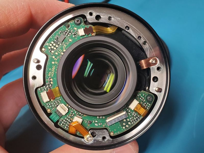
After confirming the flex cable's integrity, the rear CNC machined aluminum shell of the lens can be removed. This involves detaching two grounding straps and a push-in switch flex connector, then unscrewing four black oxide self-tapping screws that mate the shell to the central plastic lens module. With the shell lifted, the control PCB and other flex cables are exposed. Three more self-tapping screws secure the PCB, and once the flex cables are gently disconnected, the PCB can be freed for closer scrutiny.
PCB Analysis: Uncovering the Root Cause
Lens control PCBs, despite their small size, are sophisticated pieces of engineering. This C-shaped board features a main microcontroller (a Toshiba TMPM341FYXBG 32-bit Arm M3), a DC-DC converter, a motor controller, a crystal oscillator, and an array of passive components. The reverse side typically houses FPC connectors, test points, and an SPI flash package (likely a GigaDevice NOR package).
When diagnosing an unknown PCB fault, the most logical starting point is tracing the input power lines. We need to identify where V+ and Ground first enter the board and which component receives power first. On this Sigma lens, the thicker traces from the lens terminal block flex cable lead to a DC-DC buck converter. A telltale sign of a DC-DC converter is its proximity to a comparatively chunky inductor – in this case, a 2.2µH (labeled "2R2"). The specific component here is a 16-VQFN package TI TPS62140RGTR buck converter, labeled "PA71 TI 18i."
Following the input voltage rail, an inquisitive mind will spot a small, resistor-like package labeled "N" adjacent to the input filter capacitor. In camera electronics, such packages with arbitrary single-letter notation often signify an SMT (Surface Mount Technology) fuse. A quick continuity check with the multimeter confirmed it: the fuse was open, having protected the DC-DC converter from a larger failure. This 0603-sized fuse, likely a 2A fast-blow type, had done its job.
Replacing the fuse with a Panasonic 2A 32V fast blow fuse (ERB-RE2R00V) was straightforward. Desoldering the old component, cleaning the pads, and carefully soldering the new one using SMT tweezers or two fine-tipped soldering irons proved successful. The lens, once reassembled, sprang back to life, with all electronic controls functioning perfectly.
The "Why" and Further Troubleshooting
While the repair was a success, the question of why the fuse failed remains. The TI TPS62140RGTR datasheet indicates a static current limit (ILIMF) of 2.45A minimum, with a typical value of 3A and a maximum of 3.5A, due to internal propagation delays during overcurrent situations. If the lens designers indeed used a 2A fast-acting fuse, it might have been operating outside the buck converter's transient current specification, making it susceptible to blowing during brief current spikes. This highlights a critical design tradeoff between protection sensitivity and operational robustness.
If the fuse had been continuous, our next steps would involve checking the DC-DC converter's output voltage for proper specification (the Arm M3 micro requires 2.7V to 3.6V, typically 3.3V). Probing BGA-packaged microcontrollers like the Toshiba TMPM341FYXBG can be challenging due to hidden pins, but identifying wide power traces nearby can help. The availability of CAD models for Sigma lenses on GrabCAD (a generous move by Sigma!) can facilitate 3D printing jigs to power the PCB while probing.
Further advanced diagnostics might include using a logic analyzer on the unnamed circular test pads near the microcontroller, which are likely designed for factory bed-of-nails programming and testing. Discovering a UART connection here could provide boot-up sequence data. Lastly, if all else checks out, the motor controller (Rohm BU24020GU, an SPI peripheral) would be the next component to investigate for faults.
This repair underscores that even complex, modern electronics often fail at surprisingly simple points. A systematic diagnostic approach, combined with a good understanding of component function and careful execution, can bring intricate hardware back to life.
FAQ
Q: Why are JIS screwdrivers specifically recommended for camera lens repair, and what's the risk of using a Phillips head instead?
A: JIS (Japanese Industrial Standard) screws are common in camera gear due to the industry's strong presence in Japan. JIS screws have a different point angle and flatter tip compared to Phillips screws. Using a Phillips screwdriver in a JIS screw head can lead to cam-out, stripping the screw head and making it extremely difficult to remove. This is because a Phillips driver is designed to cam out at a certain torque to prevent overtightening, whereas a JIS driver is designed for better grip and direct torque transfer.
Q: What's the significance of an "N" labeled component on a PCB, especially if it resembles a resistor?
A: In camera electronics and small-scale PCBs, a two-terminal, resistor-looking surface-mount package with an arbitrary single-letter notation (like "N") or sometimes scalloped terminals is often an SMT fuse. Manufacturers may use internal part numbers or simplified markings. When troubleshooting power circuits, these components are critical to check for continuity, as they are designed to fail open to protect downstream components from overcurrent conditions.
Q: When starting to diagnose a dead camera lens PCB, what's the most effective initial troubleshooting strategy?
A: The most effective initial strategy is to always start with the power input. Trace the V+ and Ground lines from the lens's contact block onto the PCB. Identify the first major component in the power path, usually a DC-DC converter. Then, methodically check for continuity through any fuses or protection components on the input rail and verify the output voltage of the DC-DC converter. A significant portion of electronic device failures, including camera lenses, can be traced back to power delivery issues.
Related articles

Mastering Agentic AI: Building Autonomous Workflows with LangGraph
The software development landscape is evolving beyond single-prompt LLMs to autonomous AI agents capable of complex, multi-step workflows. LangChain, with its extension LangGraph, provides the essential tools to build these sophisticated systems, enabling stateful, cyclical agent behaviors. Developers can implement advanced features like Human-in-the-Loop, RAG, and streaming responses, and deploy these agents using industry best practices.

Conquering The Library: Unearthing Skulls & Terminals in Halo
'The Library' mission in *Halo: Campaign Evolved* is a notorious gauntlet against the Flood, but it also hides three game-changing skulls and a crucial lore terminal. This guide helps you navigate the relentless combat to unearth the Tilt, Pop, and Famine Skulls, as well as the Tangent III Terminal. Collecting these items enhances gameplay and deepens your understanding of the Halo universe's rich history.

ReFrame: An Open-Source EPaper Camera for Deliberate Photography
Reclaiming Intentionality in Digital Photography In an era of ubiquitous digital photography, developers often reflect on the paradox of endless captures diluting the significance of each frame. reFrame, an experimental

Amazon's Next Pillar: Custom AI Chips and Developer Implications
Fellow developers, In the rapidly evolving landscape of artificial intelligence, cloud infrastructure is a battleground, and custom silicon is emerging as a critical differentiator. Recent news from Jeff Bezos himself

in-depth: Is the Electric Trike the Next Big Thing in Shared
Veo has launched accessibility-focused electric tricycles in Denver, with plans for nationwide expansion. This move aims to diversify shared micromobility options beyond traditional bikes and scooters, offering a more stable alternative for urban transportation. The introduction of e-trikes could significantly impact how cities approach last-mile solutions.

Unlock New Gaming Worlds: Explore Microsoft & Amazon's Cloud Gaming
Cloud gaming is rapidly changing how we play, offering more flexibility and accessibility than ever before. If you're looking to dive into the world of gaming without needing a high-end console or PC, or simply want to